At my previous post I
simulated the unbalanced/balanced converter I using for
unbalanced microphone inputs and
headphone amplifier. The used chips (INA217 and TPA6120) have symmetrical inputs. These chips with balanced source have much better dynamics, noise, and sound quality. I think the selected converter I used is very good, but I wanted to simulate another solutions just for fun.
1.
This very simple schematic without required capacitors. This is the reason why the AC analysis have very good result, but with required parts the result of stability and the phases would be changed:
The AC analysis of the pure schematic:

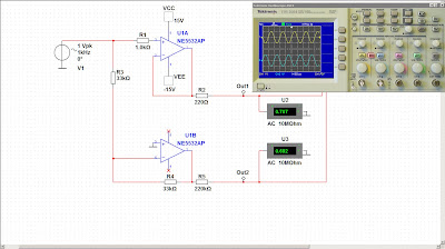
2.
This sample is more complex, but the result is not the best. The reason is that the operation amplifiers not same with inverted and non-inverted mode, but the schematic is symmetrical for - and + outputs:

The result of AC analysis:

3.
Simple "pure" solution again without capacitors and another required parts. This "base" circuit working well but with whole system have to be modified:
The AC analysis is perfect, but we got another result with required parts:

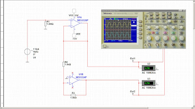
4.
On the previous 3 examples have different method negative feedback on operational amplifier. Sometime the input connected to inverted and non-inverted inputs, and the required amplifiers have several feedback. By this example the inverter circuit getting the input signal from the output of first stage. Very stable example with really good AC analysis result:
The AC analysis:

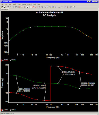
5.
The final example have more than one versions. The benefit of these schematics are the symmetrical solution of + and - outputs, which have same (or very closed) frequency responses and phases. The previous circuits have no capacitors on the negative feedback, or if have the capacitors modified the inverted stage only, the
original signal more linear than the inverted. With the current solution, the frequency response and the phase of inverted and non-inverted stages are relative parallel,
not like in the 2nd example what is serious problem.
The simplest version:

The AC analysis where the frequency responses are same, the phases are not linear, but running parallel, and the difference is very closed to required 180 degree:
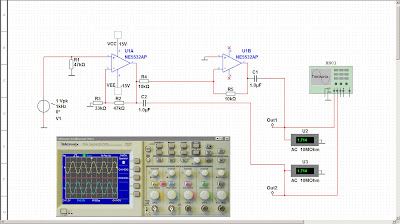
The first modification is the active feedback between the outputs and inverted input for the adjust of inverted stage output level by the R15 resistor:

The final version of this really interesting converter is two operational amplifiers added for the output. This modification have same AC result than the previous version:

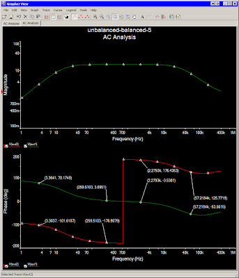
The AC analysis:
This example have gain from 707mV to 11V what is not required. If this gain is too much, modify R4/R5 and R9/R11 resistors to adjust the output gain. When the gain of stages modified, set again the output amplitude to exactly same by R15 resistor what can be trimmer potentiometer:

The result of AC analysis is very closed but modified when the gain changed:

The question is, what is the best solution if unbalanced/balanced converter required. The most simple versions are looks like perfect solutions, but with additional (and required) capacitors and with non exactly same resistors the phase and the amplitudes has been shifted. The another reason of differences is the difference between inverted and non-inverted mode of same operational amplifier stage. The simplest (and the best) schematics are block diagrams only, very good base but have to be modified. The useful solutions have two useful version: the input signal connected to same inverted and non-inverted stage. The another one is the input signal connected to non-inverted stage, and the output of this stage connected to inverted-mode operational amplifier. The another differences between the negative feedback. The second example, where the original input signal uses same stage but one with inverted one with non-inverted mode, the result is not really useful. This is the difference between modes of operational amplifiers.
The another question is the same frequency response of - and + outputs. If the original signal uses the simplest solution with direct negative feedback (like in the 1st example), and the inverted stage have negative feedback with capacitor, the frequency response (and the phases) will be different. If the
difference shows after 40kHz by AC analysis, I think the result is very useful.
The last 5th example is interesting only. Not the simplest solution, and the problem is, the phase modified by the input frequency. The difference between + and - outputs is constant 180 degree, but always modified the phase values. This is the reason why I think the one of the best result for balanced conversion is on my
previous post.
See also:


