Finally I did software simulation, what is succeed. The simulation of analog circuits are very fast and exact, very easy to measure and analyze any parameters depending on the parts, easy to get result of parts modifications by graph or by simulated measuring devices. The best is, lot of AC sources and measuring instruments are available, like function generators and oscilloscopes. I used Multisim, because the simulation of Altium is more harder, and I cannot found good examples on the net how to use Altium for simulation. But as I see, the Multisim is very popular (because easy to use, I think):

This is the schematic of one filter from the UREI 546 parametric EQ. Function generator, one channel (yelow) of oscilloscope, and U3 AC voltmeter connected to the input. Second channel of oscilloscope (blue) and U2 AC voltmeter connected to the output. The power supply is the simulation of 2x18V DC power source. On/off switch, and bypass switch included. With simulation, all switches and potentiometers are working well and real time. To see the simulation result, the circuit is very exact, same as like datasheet of original UREI device, with really small differences. The bypass switch or the Cut/Boost potentiometer on center make the output voltage to same with input. I made a movie about simulation:
I wonder, the simulation result is same as the original datasheet, or have some differences. If the result is closed to the original datasheet, I don't need expression for the modifications.
I made new schematic with simple AC voltage source instead of function generator, and I deleted the scope from the output. I used AC analysis on the output point instead of scope. The result is more useful on the graph:

Here is the frequency response of the filter. All modifications can be analyzed and displayed with graph, for example new middle frequency, Q, and Cut/Boost function of EQ between 20 Hz and 20 kHz. Later I analyzed the circuit up to 100 kHz.
With these simulations, I can't compare the results with the original datasheet. Therefore I made 4 bands with exactly same values with the original schematic. I made AC analysis with min, max, and middle frequencies of 4 bands, and compared the maximum and minimum points to the official datasheet:

The red line is the lowest frequency on all 4 bands, the blue is the another side of potentiometer, the possible highest frequency. This is the comparison with the original EQ, where is the upper frequencies are really same, the lower shows small differences. Now I think, because the simulation result and the datasheet are same with small differences, the simulation of this schematic is good idea to modify the original EQ (instead of math expressions).
This is the 5 steps of Q by the original schematic, what is same as than the graph in the datasheet:

The method of software simulation is really big help if I have to modify something. For example, this is the modified possible min and max Q with new values of parts, because for more bands I need better Q:

2 resistors are changed to make new Q values.
Here is the result of the first and last filter, from the lowest to highest possible frequencies of bands:

To make the lowest and highest frequencies of the band closer, the potentiometers changed from original 55 kOhm to new 4.7 kOhm. The lowest band on the graph have 680 nF on the integrators, the highest have 2.2 nF.
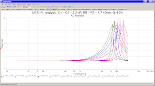
With this result, I analyzed the highest band with lower (80%) Q and compared to the result with maximum Q:

The max point of the highest band are much higher than the lowest band, I changed the possible maximum Q to lower, I modified the 80 Ohm resistor to 120 Ohm. To found the ideal resistor value for the maximum Q, I made analysis with several resistor values from 80 Ohm to original 390 Ohm:

This is the first step to design 8 bands parametric equalizer with new values.
See also:
- Simulation of UREI LP/HP filter module
- Modular, expandable parametric equalizer based on UREI546
- Simulation of 8 band parametric equalizer
- UREI546 parametric EQ like URS VST EQ bundle
- 6 and 10 bands for UREI 546 parametric equalizer
- Math expression for UREI546 parametric EQ design
- Parametric EQ Project - Modular UREI545 and 546
- Modular equalizer with gyrator filter
- PDF manual of modular gyrator EQ
- PDF manual of UREI 545 and 546 EQ clone


No comments:
Post a Comment